


|
|
|
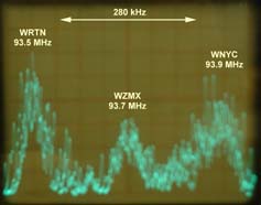
Improving FM ReceptionCompared to "ancient modulation", FM broadcasting is supposed to suppress static and eliminate heterodynes from adjacent stations. These claims may be true, but I’ve consistently experienced problems listening to FM broadcasts in most places I’ve lived. Part of the difficulty is that manufacturers of modern "Hi-Fi" receivers are spending less and less on the AM/FM tuner, while concentrating on the feature of the moment – whether it’s combined audio/video, Dolby Pro-Logic surround sound or a DTS decoder. Stereo tuners of the past included a signal strength meter and narrow/wide selectivity – when was the last time you saw those features in a modern receiver? Another problem for modern equipment is that manufacturers try to squeeze the AM/FM tuner into the same box as the digital signal processor and multiplexed display. As a result, spurious signals from the digital circuitry can find their way into a poorly shielded tuner, especially affecting the AM section. I’ve become convinced that the only equipment available with a good quality tuner is the Bose Wave Radio, some models of car radio – and the golden Hi-Fi oldies of 15 to 25 years ago. Keep your eyes open at flea markets and hamfests for vintage tuners and receivers – you may be pleasantly surprised by their superior RF performance. If you have a modern receiver with an indifferent AM/FM section, another approach is to pick up a classic Hi-Fi tuner and connect it to one of your receiver’s auxiliary inputs. For more information on vintage tuners, pay a visit to the following web pages: WTFDA FM DX Tuner overviews and Tuner Information Center. The need for improved performanceMost places I have lived are near population centers, with plenty of stations squeezed into the FM broadcast band. The transmissions I’m interested in are often of weak or medium strength, with stronger stations nearby. For example, two PBS stations from New York City present a reception challenge in my location. WNYC-FM transmits on 93.9 MHz from the Empire State Building, while WNYE-FM transmits on 91.5 MHz from a lower antenna in Brooklyn. Take a look at all the stations in my area adjacent to 91.5MHz and 93.9MHz:
(In December 2001, WNYC-FM was only using a 1kW temporary transmitter. By May 2002 they were using full power, but from their new standby location on the Conde Nast Building at 4 Times Square. In November 2002, WNYC-FM transferred to the Empire State Building master antenna at full power.) The typical 10.7 MHz IF filter used in a modern Hi-Fi receiver has a 3dB bandwidth of 280 kHz. If you take a look at a spectrum analyzer display of a typical part of the VHF-FM band, you will see why 280 kHz is far too wide a bandwidth for this crowded neighborhood.
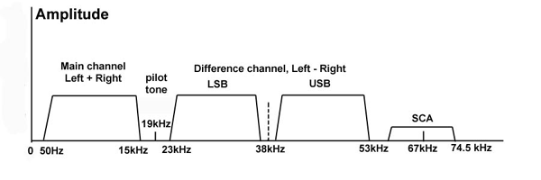
Here’s a reminder of what the modulating signal looks like for a multiplex stereo signal combined with a 67 kHz SCA ("storecasting") signal. The main audio signal (left + right) occupies an audio bandwidth between 50 Hz and 15kHz. The 19 kHz pilot tone is used by the stereo receiver to reconstitute the 38 kHz suppressed carrier, which is needed to demodulate the double sideband (DSB) L-R difference audio signal, containing the left-minus-right component. The spectrum above 53 kHz may contain SCA signals, which take the form of a narrow-band frequency modulated carrier at e.g. 67 kHz. There can be additional subcarriers for data emissions.
Unfortunately, when receiving frequency modulation, you cannot reduce the I.F. bandwidth too much or the signal will start to distort. For stereo reception, a bandwidth of 180 kHz or even 150 kHz will be quite satisfactory. If you don’t mind listening in mono, the bandwidth can be reduced even further before distortion sets in. What's your problem?Before you start making a lot of modifications to your own FM receiving setup, it’s worth diagnosing your problems as accurately as possible. - Are you really suffering from adjacent channel interference? A station on the adjacent channel can sometimes overwhelm the desired station, but at other times the effect can be more subtle. It may appear as a high frequency audio "tizz" coinciding with modulation peaks from the adjacent station. This can be especially noticeable during quiet passages from the station you are listening to. Sometimes the effect is to raise the background noise on the stereo carrier you are listening to – once again this will be especially noticeable during quiet passages or silences. Try switching back and forth between mono and stereo reception to see how much the noise rises on stereo. Don’t forget that you’ll also get a significant increase in noise between mono and stereo if the signal strength of the desired transmission is poor. You should check all the frequency allocations for your area. Here are some U.S. sites worth visiting for this type of information: Broadcast Station Location Page, FCC FM Radio Database Query, 100000 Watts US Radio & TV Directory and specific to my area: New York Radio Guide, Northeast Radio Guide. There are other causes of interference in addition to signals in the adjacent channel. Noise from electrical sparking is one possibility. Radiation from nearby computer equipment is another. If there is a powerful radio or TV station nearby, then inter-modulation could be involved -- you might benefit from an older-style analog tuner with plenty of RF selectivity. - Could you improve reception with a better antenna? If your investigations show that the desired stations are mostly in one direction and the undesired station(s) are in a different direction, then it may be possible to improve reception with a directional antenna. The best location is outside, as high as possible, but good results are also possible with a Yagi antenna in the roof space. - Could you improve your FM receiver? An inexpensive stereo receiver might not have very good IF selectivity. Perhaps a better quality receiver would give you better performance? (But don’t bank on it!) It really is adjacent channel interference – so what to do?
Some manufacturers produced a high performance tuner for Europe and an inferior version for North America. European FM band plans employ a 100 kHz transmitter channel spacing, much tighter than the 200 kHz spacing for North America. The difference in tuner performance is usually achieved by incorporating additional I.F. bandpass ceramic filters, possibly with additional stages of I.F amplification. North America readers -- if you come across a receiver or tuner designed for Europe, it may be worth considering for the improved performance. Just remember that Europe has different standards for AC power (230-240V AC at 50Hz instead of 110V-120V 60Hz), AM channel spacing (9kHz instead of 10kHz) and FM de-emphasis (50 microseconds for Europe instead of 75ms for North America). If these items cannot be switched to the U.S. standards, the unit might not be such a good choice. Do it yourself improvements
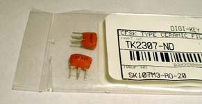
I strongly recommend a visit to the following web page: http://pages.cthome.net/fmdx/filter.html, where Mike Bugaj provides practical instructions for replacing the 10.7MHz ceramic filters found in many FM tuners. Mike recommends use of IC sockets to allow easy plugging and unplugging of the 3-pin ceramic filters you will substitute. This allows you to choose the best filter bandwidth for your circumstances – and even allows you to restore the tuner to its previous performance by plugging the original manufacturer’s filters back in.
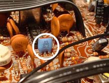
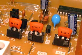
Ceramic filter replacementThe steps you need to go through are as follows. 1. Make a note of the current performance of your tuner or receiver. If there is a signal strength meter, note the reading and signal quality for station(s) you wish to receive. 2. Disconnect the tuner or receiver, unplug AC power and remove the unit's cover and any metal shields that are necessary to reveal the I.F. strip. Locate the RF tuner and FM IF strip, then identify the 3-pin 10.7 MHz ceramic IF filters. (The more filters present, the better the selectivity will be. One filter – pretty bad. Two filters – not so good. Three or more – definitely better... They might be designated as "CF1", "CF2", "CF3" or "X101", "X102", "X103" etc.) 3. You may have to remove additional covers or lift the printed wiring board in order to reach the I.F. board’s solder side. Using a solder sucker or desoldering braid, carefully unsolder each of the 3-pin 10.7 MHz ceramic filters. Don’t throw the old filters away – you may want to restore them later or recycle them into another radio. 4. You can solder the new filters directly onto the board, or to allow experimentation, follow Mike Bugaj’s advice and install 3-pin sockets, cut from a DIL IC socket. 5. Replace the old filters with narrower types. Hint: start off with 180 kHz bandwidth filters and see whether they provide sufficient rejection of adjacent channel signals. If you need a narrower bandwidth, replace one or more of the 180 kHz filters with 150 kHz bandwidth filters. 6. Replace shield covers and apply power. If you have an old-style analog tuner/receiver with a manual tuning dial, you will probably find that tuning in stations is more critical with the narrower IF selectivity. A digital tuner should tune the same as before. 7. Check the signal strength and quality of reception for the stations you noted earlier. The strength may have been reduced somewhat, especially if you substituted narrower 150kHz filters. The tuner might have preset controls for IF gain and/or S-meter reading. If so, you may be able to adjust the S-meter reading to the same as before. If not, you might have to restore some of the filters and accept a compromise between better selectivity and adequate signal strength. Another possibility is to add on one more stage of IF amplification – especially if the circuit board has space for it already. 8. When you have reached a satisfactory performance, replace all covers and reconnect the tuner. Check signal strengths again, then relax and listen to your favorite stations very carefully. The ultimate test is whether you made an improvement to the overall quality of reception and the only equipment you need to make an assessment is your own ears. Tune around and you may be able to hear weak signals that were previously inaudible, covered up by strong signals on the adjacent channel.
- 73 de Malcolm, NM9J |
|
G3VNQ-NM9J amateur radio site, 05-Jun-2007 |